Video Gallery
SITEMA Frequently asked questions
How Far Does the Load Sink When the Safety Catcher is at Zero Pressure?
How Do You Unlock the Sitema Safety Catcher?
What is the Typical Reaction Time of the Safety Catcher?
What is the Maximum Force Mounting Components Should Be Designed For?
What Happens if Oil Gets on the Shaft? Do I Lose Holding Capacity?
How Do I Size the Safety Catcher?
What is the Safety Factor of the Safety Catcher?
Are Safety Catchers Used for Accurate Positioning?
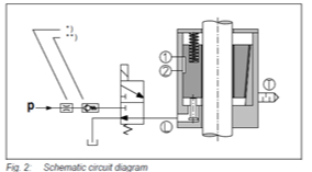
What Control Circuit Do You Recommend for the Sitema Safety Catcher?

* In case impact noises due to excess pressure are audible when pressurizing the safety catcher, these can be suppressed by means of a flow control valve in the p-line.
** In case the pressure is not sufficiently constant (e.g. pressure drop at the beginning of a downward stroke), we recommend a check valve in the p-connection of the valve.
PRESSURE FLUIDS
To keep the clamping permanently open, safety catchers mostly are hydraulically actuated. Pneumatic versions are also available for smaller units.
- Hydraulic Actuation:Hydraulic oil (HLP) in accordance with DIN 51524-2:2006 must be used as pressure fluid. Please consult SITEMA before using any other fluids.
- Pneumatic Actuation:The compressed air must be dried and filtered. SITEMA recommends compressed air according to ISO 8573-1:2010 [7:4:4].
ACTUATION WITH A 3/2-WAY VALVE
In most applications an actuation as suggested in Fig. 2 is used. During every operational cycle, the 3/2-way valve is actuated electrically and releases the safety catcher.
In all other operational conditions, as well as in cases of power-failure, pressure line breakage, emergency stop, etc. the safety catcher becomes effective, secures the rod and/or stops the load. If necessary the valve can also be switched by another safety signal, e.g. speeding, contouring error, etc.
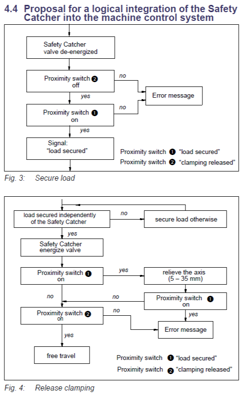
MONITORING BY PROXIMITY SWITCHES
Proximity switch 1 “load secured” signals the secure state and is used to authorize entrance to the danger zone. Proximity switch 2 “clamping release” is used to activate the movement of the drive in the load direction. For automatic detection of failures both signals are compared. In case both switches indicate the same state—apart from minor overlapping periods—there is a defect present.
